Learn from others mistakes
- Safe Work
Connections and terminations
When carrying out electrical work you need to make sure your connections and terminations are secure and reliable to avoid problems associated with loose terminals and conductor breakage.
Flexible cord has not been secured
Flexible cord connections do not have adequate mechanical protection.
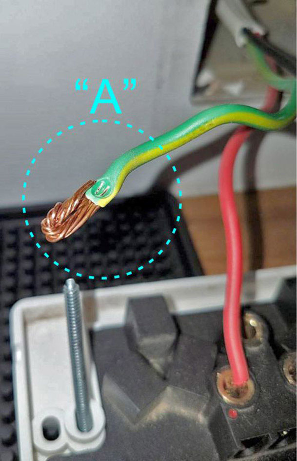
Here is an example of a flexible cord that has not been secured correctly.

Identified risks
Issue A
There is no restraint on the flexible cord meaning the connections are more vulnerable to breakage resulting in the loss of protective earth.
Should the flexible cord be pulled or placed under tension some or all of those connections could be severed. It could be possible for the protective earth conductor connection to be broken and for the phase and neutral connections to remain intact.
This could result in the flexible cord continuing to supply power without a protective earth conductor. In the event of a fault this could create a serious safety risk.
Wiring rules
The flexible cord should be installed so that any stress on the connections is relieved by a restraining device such as a gland. See AS/NZS 3000 2007 clause 3.7.2.8;
Connections should provide appropriate level of insulation and mechanical strength. See AS/NZS 3000 2007 3.7.1;
 Good work practices
When joining flexible cords, which could be subject to tension or pulling, it is good practice to ensure the earth conductor has the longest length in relation to the active conductors. Should the flex connections be subject to pulling or stress and become detached the active conductors would be disconnected before the protective earth connection was broken. In this situation any appliance or equipment the flex was supplying would retain a protective earth after the connections to the active conductor were broken.
Knotting the flexible cord as a means of creating a restraining device to protect connections against pulling or tension is not permitted. See AS/NZS 3000 2007 clause 3.7.2.8.
To maintain the IP rating of the enclosure, always follow the manufactures installation instructions; the fixing fasteners should be always located in the recessed sealable mounting locations not penetrating through the base in other locations as in this example.
Unreliable protective earth termination
The electrical continuity of the earth conductor has been reduced.
The terminal screw has not made proper contact to the earth wire.
Identified risks
Issue A
The earthing contacts of the socket outlet may not be earthed or have an unacceptable high earth resistance.
In the event of a phase to earth fault in an earthed appliance that is plugged into the socket, the protective device may not operate and the faulty appliance could remain live.
The terminal screw has clamped directly to the insulation instead of the bare copper as it has been designed to do. There is no direct pressure on the bare copper inside the terminal and over a period of time the connection may deteriorate to a point where there is a higher resistance or no earth connection.
Automatic disconnection of supply in the event of a short circuit to a plugged-in earthed appliance may not activate.
Wiring rules
Connections and terminations should always provide reliability and electrical continuity. See AS/NZS 3000 2007 clause 3.1.2;
Earthing contacts of every socket-outlet shall be earthed. See AS/NZS 3000 2007 clause 5.4.2;
Good work practices
To ensure secure and reliable connections, appropriate care and visual checking should be carried out on all terminations and connections.
The electrical continuity of the connection should be no less than the conductor itself.
Testing with a voltmeter between the phase and earth socket contacts may have indicated approximately 230V, but does not verify the resistance or conductivity or effectiveness of the connection.
Carrying out an earth fault loop impedance test to verify the impedance of the circuit conductors at the switch socket can also be used to identify high resistance connections.
Conductor too large for the terminal
The electrical continuity of the neutral conductor has been reduced.
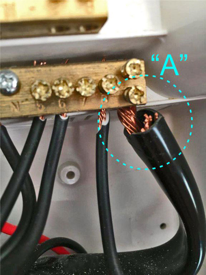
The main neutral screen conductor has copper stands “cut out” so it can fit inside the terminal of the neutral bar.
Identified risks
Issue A
The main neutral conductor of this neutral screen cable has had a number of strands removed to facilitate the termination of the conductor into the tunnel type terminal.
The main neutral provides the essential earth fault loop path connection from the neutral and earth bar to the star point of the supply transformer through the network supply and distribution lines. Any reduction in the cross-sectional area of the neutral could compromise the effectiveness of the earth fault loop path in addition to reducing the current carrying capacity of the neutral.
Terminals are rated to accept specific conductor type and sizes. If the conductor is too large or too small for the terminal, poor connections, and loose terminations may result, in overheating creating fire risks.
Wiring rules
Connections and terminations should always provide reliability and electrical continuity. See AS/NZS 3000 2007 clause 3.1.2;
Connection methods must be suitable for the application. See AS/NZS 3000 2007 3.7.;
Single-phase consumer mains or submains neutral conductor to have a current carrying capacity not less than the phase conductor. See AS/NZS 3000 2007 3.5.2:
Good work practices
The terminal must be suitable for the cross-sectional area of conductor so it can be inserted into the terminal without excessive force.
Never reduce the cross-sectional area of a conductor in order to make it “fit” into a terminal that is too small.
The electrical continuity of the connection should be no less than the conductor itself. Always use a terminal that is compatible with the size of the conductor.
When connecting the neutral screen take care to apply the right tension when twisting the stands to ensure even and correct cross-sectional area so the conductor can be placed correctly within the terminal.